Temperature & Pressure Reducing Valves
Features
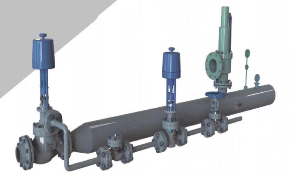
Temperature & Pressure reducing device is a new generation product developed by absorbing the advanced technology and structure of temperature and pressure relief at home and abroad.
It composed of four parts: Temperature &Pressure reducing valve, vapour pipe, temperature reducing water pipe and thermal regulating device.
• Standard: NB/T 47033
Applications:
the Temperature &Pressure reducing devices are used in power plants, industrial boilers, thermal power plants, etc., to reduce the temperature and pressure of the primary (new) steam pressure P1 and temperature D1, so that the secondary steam pressure P2 and temperature T2 can reach the values required by the production process. WY series temperature and pressure reducing device and its supporting automatic control cabinet have comprehensive functions of measurement and control, and are widely used in power station, petrochemical, light industry, metallurgy and other industrial departments as well as urban heating and heating systems.
• Inlet pressure and temperature: Low pressure P1 ≤ 1.0MPa, T1 ≤ 300℃;
Medium pressure P1 ≤ 4.0MPa, T1 ≤ 450℃;
Secondary high voltage P1 ≤ 5.4MPa. T1 ≤ 485℃;
High temperature and high pressure P1 ≤ 20MPa, T1 ≤ 570℃;
•Outlet steam pressure: Outlet steam pressure P2 and temperature T2 shall be the values required by the user, and the adjustment accuracy shall not be lower than 2.5.
•Noise range: During normal operation of the device, the noise of the well 1 m downstream of the same horizontal plane at the outlet centerline of the temperature and pressure reducing reading (pressure reducing regulating) device is measured at a distance of 1 m from the pipe wall, and the overall noise level should be no more than 85dB (A).
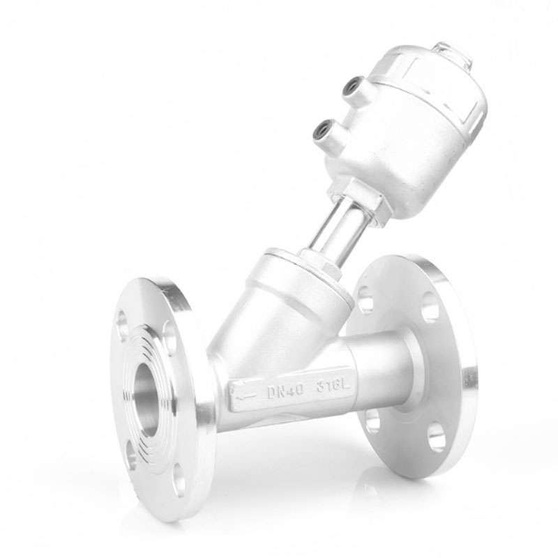
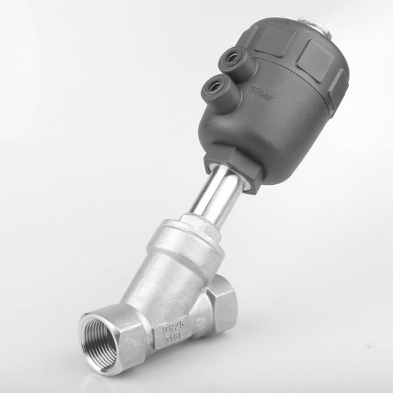
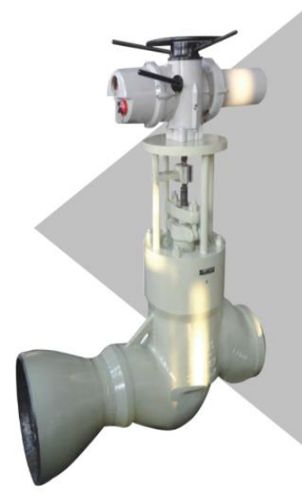
Temperature & Pressure Reducing Valve
Features:
The valve cover adopts self sealing structure or flange type, cage type sleeve plunger valve core, single seat cone seal, and high leakage level. The sealing surface is stacked with cemented carbide, and the inner surface is sprayed with impact resistant materials, with long service life. The seal is metal wound gasket and reinforced flexible graphite, reliable sealing. No vibration.
Applications:
It is used for water supply flow regulation, with reliable sealing, high leakage level and long service life. Water supply bypass, spray desuperheating system.
• Nominal Pressure: P5450V-P57200V
• Nominal Dimension: DN50~DN300
• Adjustment Range: 20:1-100:1
• Main Material: WCB, WC6, ZG20CrMo, 12Cr1MoV
• Operating Temperature: -29℃~570℃
• Applicable Intermediaries: Vapour
• Connection Mode: Flange, Welding
•Transmission Mode: Electric, Pneumatic
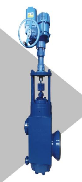
High Temperature &Pressure Reducing Valve
Features:
The valve adopts cage type porous structure, with good adjustment, no noise and no vibration. The internals can adopt single-stage or multi-stage throttling, which is applicable to high-pressure differential working conditions. The pressure reduction is completed in one valve. Considering the high temperature conditions, the internal adjustment and coordination are reasonable, and the operation is flexible. The valve cover is designed as a self sealing adjusting cover, which is suitable for working conditions of high temperature and high pressure media. The sealing surface of the valve seat is piled with cemented carbide, and the surface of the free core is sprayed with cemented carbide, which is erosion resistant and has a long service life. Single valve seat cone sealing surface, reliable sealing, less leakage and good at self-cleaning.
Applications:
Flow and pressure control of steam turbine bypass and superheated steam bypass. Steam control and pipe warming of boiler soot blowing system. High steam pressure regulation of warm and high-pressure steam pipeline.
High-pressure System Valve
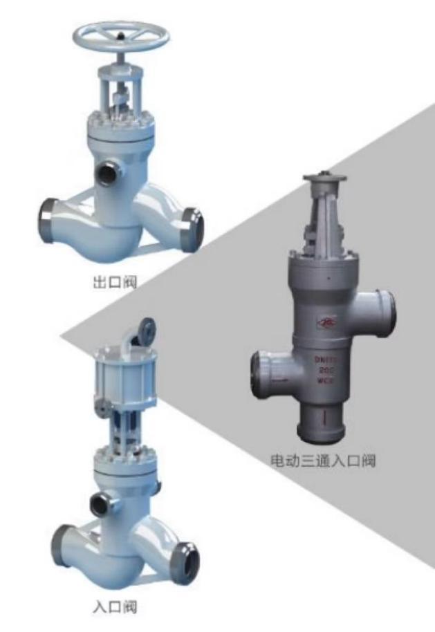
Features:
The inlet valve is used together with the check valve. After the high-pressure heater is filled with water, the pressure of the water increases continuously. When the pressure rises to a certain value, the valve rod moves upward with the help of the differential pressure acting on the valve stem section of the inlet valve to open a channel into the high-pressure heater, allowing water to enter the high-pressure heater. At this time, the high-pressure heater is put into operation. When the pipeline system of the high-pressure heater breaks by accident, and the water level in the high-pressure heater exceeds the allowable value, the water level signal opens the quick opening and closing valve through the electrical device, the condensate enters the piston cylinder above the inlet valve, presses down the piston, pushes the regulating relay down, closes the inlet of the high-pressure heater, opens the bypass, and high-pressure heating The device stops running, and the whole action time is 2 seconds.
• Standard: NB/T 47044, ASME B16.34,JB/T 3595
• Nominal Pressure: PN16-PN420(CLASS900-CLASS2500)
• Nominal Dimension: DN100~DN350(4”-14”)
• Main Material: 1.WCB, ZG20CrMo, Cr5Mo, ZG20CrMoV
2.25#, 12Cr1MoV
3.ASTM A216 WCB, ASTM A217 WC6, , ASTM A217 WC9
4.ASTM A105, ASTM A182 F11, ASTM A182 F22
• Operating Temperature: 1. WCB: -29℃~425℃
2. Alloy Steel: -29℃~540℃, -29℃~570℃
• Applicable Intermediaries: Water, Steam
• Connection Mode: Welding
• Transmission Mode: Manual, Electric, Hydraulic
Hydrostatic Testing Valve
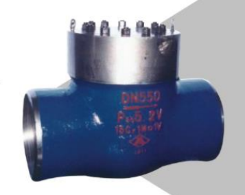
Features:
It is installed on the overheater outlet of the boiler and the inlet and outlet steam pipes of the reheater as the isolation during the hydrostatic test. After water pressure, remove the internal blocking plate as a pipe. The blanking plate can be installed again during the next hydrostatic test.
Applications:
1. The pressure self tightening sealing structure is adopted, and the branch pipes at both ends are welded.
2. The flat O-ring seal is adopted, and the valve seat is made of stainless steel by surfacing welding.
3. The blanking plate shall be inserted during the hydrostatic test, and taken out after the hydrostatic test. Multiple hydrostatic tests can be conducted.• Standard: JB/T 12002,NB/T 47044 ASME B16.34
• Nominal Pressure: PN16-PN420(CLASS150-CLASS2500), P54100V-P57200V
• Nominal Dimension: DN100~DN1000(4”-48”)
• Main Material: 1.WCB, ZG20CrMo, Cr5Mo, ZG20CrMoV, ZG15Cr1MoV
2.25#, 12Cr1MoV
3.ASTM A216 WCB, ASTM A217 WC6, , ASTM A217 WC9, ASTM A217 C12A
4.ASTM A105, ASTM A182 F11, ASTM A182 F22, ASTM A182 F91, A182 F92
• Operating Temperature: 1. WCB: -29℃~425℃
2. Alloy Steel: -29℃~540℃, -29℃~570℃
3. F91: -29℃~610℃
• Applicable Intermediaries: Water, Steam
• Connection Mode: Welding
• Transmission Mode: /
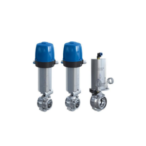
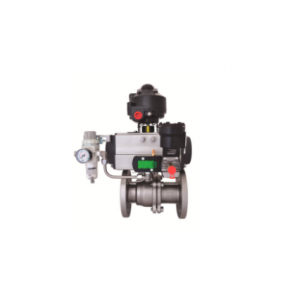
Product Display